SET UP YOUR SDI ACCELEROMETER
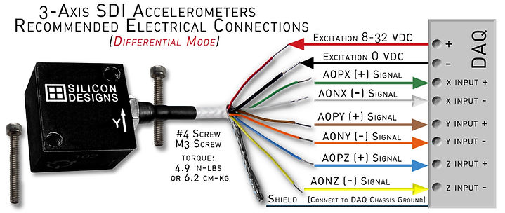
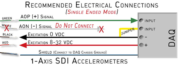
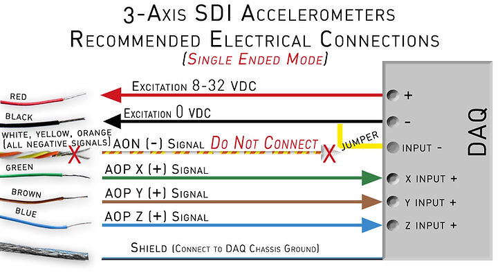
SDI's Industrial Test & Measurement MEMS DC Accelerometer modules are extremely simple to set up and operate. Excitation power is either a steady 5V or a range from 8-32V, depending upon the model. Each axis requires one channel on a data acquisition system (DAQ), so a 1-axis module uses one and a 3-axis module uses up to three if all axis are being used. All models support differential and single-ended outputs, and wiring examples are below.
ESD PRECAUTIONS
Before removing unit from antistatic bag, attach a ground strap to protect your accelerometer. Anti-static handling precautions are HIGHLY recommended. The accelerometer will arrive in an ESD bag or case – we suggest keeping this for reference and future use.
PHYSICAL SETUP
Attach your module to its intended location using the method of your choice. The surface must be very flat and free of debris. Use care not to overtax the cable by bending it harshly or placing it in a location that will cause excessive wear.
-
Use a small drop of glue, epoxy, or other adhesive
-
Attached to a block or stud-type mount with screws or bolts
-
Attach directly to the surface with screws and bolts
-
Make sure not to over-torque when using screws or bolts.
-
Maximum dry torque values for non-plated screws:
-
1/4-20 (for 2230 mounting block) / 6 ft-lbs
-
M6x1 (for 2230 mounting block) / 100 kpsi
-
#4-40 coarse thread / 4.9 in-lbs = 78 in-oz
-
#4-40 coarse thread / 10 in-lbs = 160 in-oz
-
3 mm coarse thread / 6.2 cm-kg = 86 in-oz
-
3 mm coarse thread / 112.7 cm-kg = 176 in-oz
-
For fine thread, increase these values by 9%
-
For plated screws decrease torque to 66% of these values
-
If lubricating oil is used, decrease torque to 40% of these values
Before connecting the accelerometer wiring, make certain all equipment is turned off.
INITIAL SETUP - DIFFERENTIAL
To achieve the highest resolution and lowest noise performance from your SDI accelerometer, SDI recommends connecting it to your voltage measurement instrument in a differential configuration using both the AOP and AON output signals.
To configure the connections for DIFFERENTIAL MODE, use the diagrams below to connect the signal wires, then connect red wire, then black wire, then shield/ground wire.
-
Make sure your power source is appropriate for your SDI product. Some only require 5V DC. Excessive voltage will damage the accelerometer irreparably.
Once connected, set the data acquisition system to the appropriate range: ±4 volts in differential mode, or .5 to +4.5 in single ended mode.


INITIAL SETUP - SINGLE ENDED
To configure the connections for SINGLE ENDED MODE, do not connect the negative signal wires and use a jumper from the black wire to an unused negative signal input location on the DAQ that corresponds with the positive signal wire(s).

