MEASURE TILT
SDI’s analog ±2G surface mount accelerometers, as well as all SDI modules built with them, have the low noise performance necessary for measurement accuracy in tilt applications.
CALCULATIONS
At room temperature:
Vout = Bias + a x Scale Factor
or
V = B + a x S
In tilt applications,
a = g cos(theta)
where theta is the angle between the sensitive axis and gravity measured in radians.
This gives
V = B + S x g x cos(theta)
The resolution of the sensor is the change in output, V, for a given change in input, theta,
R = dV/d(theta)
making
R = -g x S x sin (theta)
RELATIONSHIP BETWEEN SIGNAL OUTPUT V AND RESOLUTION
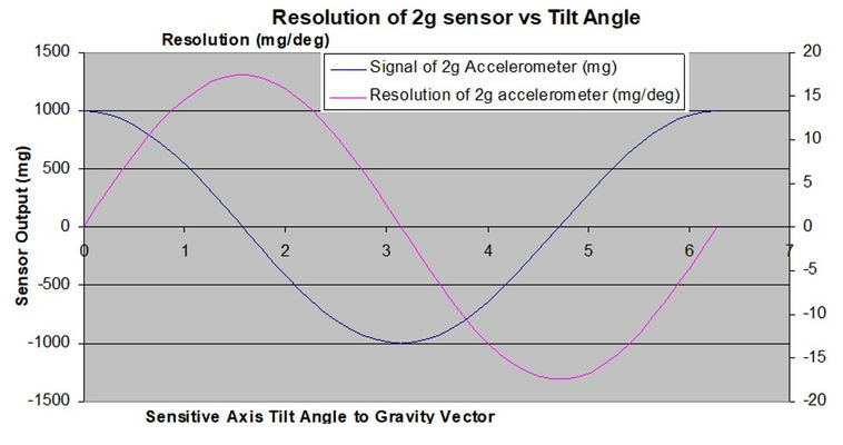
In the graph below, the resolution is maximum when the signal V is minimum. That is, in the so-called "zero-g" position when the sensitive axis is orthogonal to the gravitational acceleration, the sensitivity is at its highest. Inversely, when the sensor is in the +1 or -1 g position, i.e. when the sensitive axis is parallel to the gravitational acceleration, and the signal is maximum, the resolution is at a minimum (zero).

Note that this relation is exactly the same for any 2g sensor, regardless of manufacturer. The maximum resolution of a ±2G accelerometer by definition is 17.453 mg/deg and occurs when the sensitive axis is perpendicular to the gravity vector.
UNDERSTANDING NOISE SPECIFICATIONS AS A FUNCTION OF TILT SENSOR ACCURACY
When selecting a tilt sensor, a critical specification parameter for consideration is noise. For example, the noise level specification of the ±2G version of Silicon Designs Model 1521 industrial-grade surface mount MEMS DC accelerometer is:
With this noise specification, a typical noise error for a 1Hz bandwidth measurement would be:
In contrast, if another accelerometer manufacturer’s ±2G sensor has a noise spec of 20ug/root Hz, then the equivalent error would be four times as great, or
In this example, based upon a comparison of the two noise specifications of these ±2G parts, the SDI Model 1521 accelerometer would be three times more accurate for tilt sensing.
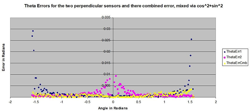
Note that by using two sensors mounted perpendicularly, the sensitivity vs angle curve can be flattened. Each sensor will have its own estimate of the angular error. For example, if tilt sensor A is mounted with the sensitive axis in line with the gravity vector, and tilt sensor B is positioned with its sensitive axis perpendicular to gravity, then two separate estimates of theta are provided, one from sensor A and one from sensor B.
If these estimates are combined according to the formula:
Then the combined angular error can be flattened over the actual input error. The chart below shows a simple excel simulation of this. Angular error values for the estimates of theta for tilt sensors A and B are plotted in purple and blue respectively. Note that the error from tilt sensor A is maximum when theta is zero and the sensor is in the +1G position but goes down as the sensor is turned to the zero g position.
